History of SQL and Data Modelling
History of SQL
- SQL, short for Structured Query Language, began its journey in the 1970s within IBM’s System R project. The goal was to develop a database management system capable of efficiently handling structured data.
- Originally, the language was dubbed SEQUEL (Structured English Query Language). However, due to trademark conflicts, it had to be renamed. Thus, SQL, which stands for Structured Query Language, was born.
- The core concept of SQL is derived from Edgar F. Codd’s relational model, which emphasizes organizing data into tables with defined relationships between them.
- Over time, SQL became the de facto standard for interacting with relational databases, offering a powerful and standardized way to retrieve, manipulate, and manage data.
- The language’s widespread adoption led to standardization efforts by ANSI (American National Standards Institute) and ISO (International Organization for Standardization), ensuring consistency and compatibility across different database systems and vendors.
- Today, SQL plays a crucial role in various applications and industries, enabling organizations to efficiently store, retrieve, and analyze structured data to derive valuable insights and make informed decisions.
Now lets understand about Data Modelling and Database
Data Modelling:
Data Modelling is like making a plan for how data will be organized. It uses diagrams or symbols to show relationships between different pieces of information. This helps keep things consistent and easy to access, no matter what the data is used for.
Advantages of Data Modelling :
Data Modelling offers several key benefits:
- It assists in identifying the appropriate data sources for populating the model.
- Enhances communication across the organization.
- Facilitates documentation of data mapping within the ETL (Extract, Transform, Load) process.
- Enables querying of database data and the generation of diverse reports, thereby supporting data analysis through reports.
Terminology in Data Modelling
- Entity: Entities represent objects or items within a business environment that require data storage. They define the subject matter of a table. For example, in an e-commerce system, entities could include Customers, Orders, or Products.
- Attribute: Attributes organize and structure the data within an entity by representing its specific characteristics or properties. For instance, attributes of a Customer entity may include Name, Address, and Email.
- Relationship: Relationships illustrate the connections or associations between entities, elucidating their interactions and dependencies. For instance, the relationship between Customers and Orders signifies that a customer can place multiple orders.
- Reference Table: A reference table resolves many-to-many relationships between entities, transforming them into one-to-many or many-to-one relationships. For example, in a system with Customers and Products, a reference table like OrderDetails can link customers with the products they have ordered.
- Database Logical Design: This involves crafting the database within a particular data model of a database management system, outlining its structure, relationships, and rules at a conceptual level.
- Logical Design: This stage focuses on creating keys, tables, rules, and constraints within the database, emphasizing the logical structure and organization of data without delving into specific implementation details.
- Database Physical Design: Here, decisions are made concerning file organization, storage design, and indexing techniques to ensure efficient data storage and retrieval within the database.
- Physical Model: This represents the database considering implementation-specific details like file formats, storage mechanisms, and index structures. It transforms the logical design into an actual database implementation.
- Schema: A schema provides a comprehensive description or blueprint of the database, defining the structure, relationships, constraints, and permissions associated with its objects.
- Logical Schema: This represents the theoretical design of a database, akin to drawing a structural diagram of a house during the initial stages of database design. It aids in visualizing the relationships and organization of database entities and attributes.
Data Abstraction Levels
Data Modelling involves several levels of abstraction, including
- Conceptual Level: At this highest level of abstraction, the focus is on determining what data needs to be stored and how it relates to each other. Visual representations such as diagrams are often used to illustrate these relationships. For example, one might decide to store data about customers, products, and orders, establishing relationships between customers and orders, as well as between products and orders.
- Logical Level: Positioned in the middle of abstraction levels, the logical level deals with how the data will be stored and organized. Data modeling languages like SQL or Entity-Relationship (ER) diagrams are commonly employed to depict this organization. For instance, one might choose to utilize a relational database, creating tables for customers, products, and orders, and defining relationships between these tables.
- Physical Level: This level represents the most basic or lowest level of abstraction, concerning the specific details of how the data will be stored on disk. Technical aspects such as data types, indexes, and storage mechanisms fall under this category. For example, one might decide to store the data in a specific database server, utilize specific data types for each column, and implement indexes to enhance query performance.
Perspectives of a Data Model:
Network Model
The Network Model represents data as interconnected records with predefined relationships. It allows for many-to-many relationships and uses a graph-like structure. For example, in a company’s database, employees can work on multiple projects, and each project can have multiple employees assigned to it. The Network Model connects employee records to project records through relationship pointers, enabling flexible relationships.

Image Reference : https://simple.wikipedia.org/wiki/Network_model_(database)
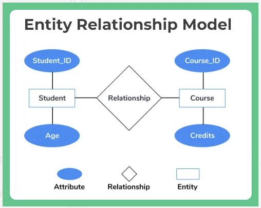
E-R (Entity- Relationship) Model
The ER (Entity-Relationship) Model organizes data through entities, attributes, and relationships. Entities represent real-world objects, attributes define their characteristics, and relationships illustrate connections between entities. For instance, in a university database, entities like Students and Courses would have attributes such as student ID and course name. Relationships, like “Student enrolls in Course,” demonstrate the associations between these entities.
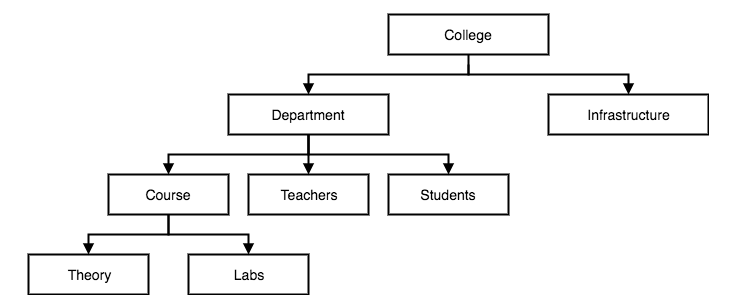
Hierarchical Model:
In the hierarchical model, data is organized in a tree-like structure, with parent-child relationships. Each record has one parent and multiple children. This model is exemplified by organizational hierarchies, where the CEO occupies the top position, followed by managers, employees, and department heads. These hierarchical connections are visually depicted in the hierarchical model, enabling navigation either from the top to bottom or vice versa.
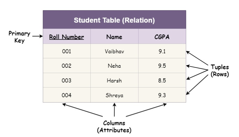
Relational Model :
The Relational Model structures data into tables comprising rows and columns. It establishes relationships between tables using primary and foreign keys. For instance, in a customer and orders scenario, customer details are stored in one table, while order information is stored in another. The Relational Model links these tables using a common key, such as a customer ID, to associate relevant records.